The Real Problem in Switchgear Insulation Design
Switchgear insulation design is a system-level engineering challenge, not a simple process of adding insulating material wherever discharge appears. In impulse withstand voltage tests, blindly “patching” weak points may suppress flashover temporarily, but it rarely addresses the root cause and often introduces new risks.
The decisive factor behind most insulation failures is electric field distribution, not insufficient insulation thickness. Effective switchgear insulation design focuses on controlling high electric field intensity regions instead of stacking materials.
Why Electric Field Distribution Matters More Than Insulation Thickness
Partial discharge and breakdown are triggered when local electric field strength exceeds material limits. Adding insulation without reshaping the electric field often shifts stress to adjacent air gaps, making failures more likely. In practice, optimizing electric field distribution delivers far greater improvements than increasing insulation thickness.
This principle is fundamental to reliable switchgear insulation design, especially under impulse voltage conditions.
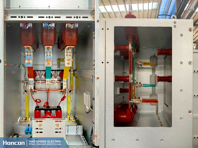
Busbar Geometry: A Critical Factor Often Overlooked
Busbar selection directly affects electric field uniformity. Rectangular copper busbars, such as 6 × 30 mm conductors, create sharp edges that concentrate electric fields and perform poorly during impulse tests. In contrast, a Φ100 mm tubular busbar distributes the electric field smoothly and significantly improves impulse withstand performance without increasing insulation.
This example highlights how geometry plays a decisive role in switchgear insulation design.
Dielectric Constant and Voltage Distribution in Insulation Systems
When different insulation media are connected in series, voltage division depends on capacitance rather than thickness. Materials with higher dielectric constants carry lower voltage, forcing higher electric field stress into neighboring air gaps.
Epoxy resin typically has a dielectric constant of 2.5–6.0, while FR-4 insulation boards range from 4.2–4.7. Improper material combinations can unintentionally distort electric field distribution, undermining switchgear insulation design.
Insulation Board Placement: A Common Design Pitfall
A frequent mistake is mounting phase-to-ground insulation boards directly against metal side panels. This sharply increases electric field strength in the remaining air layer and degrades negative polarity impulse performance.
Correct switchgear insulation design requires centered insulation board placement to achieve balanced electric field distribution.
A simplified calculation shows that with a 40 mm phase spacing, a centered 10 mm epoxy board (ε = 4) under a 75 kV impulse results in an air-gap field strength of 2.308 kV/mm—about 23% higher than the case without insulation. In this scenario, blindly adding insulation worsens the risk.
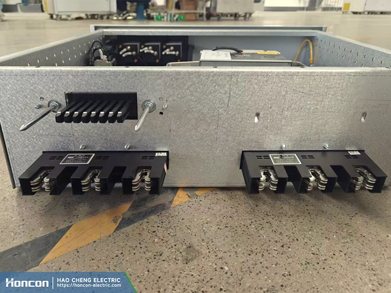
A System-Level Approach to Reliable Switchgear Insulation Design
Based on these principles, our complete switchgear systems adopt a holistic switchgear insulation design approach from the very beginning. Through electric field simulation, tubular busbars, centered insulation layouts, and modular shielding structures, we achieve uniform electric field distribution at the system level.
Extensive impulse testing confirms stable compliance without excessive material stacking, making our solutions ideal for renewable energy projects, prefabricated substations, and complex distribution environments.
Looking for a reliable switchgear supplier? Please contact Guang Dong Hao Cheng Electric Co., Ltd.
Please subscribe to our Youtube Channel to know more: Honcon.